Piece by Piece: Overhead Cranes Explained – Part 3 – Bridges
/ Blog
Overhead cranes are large structures that are composed of smaller parts that all work together in perfect coordination. The trolley, bridge, cab, and control house are all parts of an overhead crane that make up these great machines. Today, our Piece by Piece series is breaking down the crane’s bridge.
If you haven’t already, review Piece by Piece: Overhead Cranes Explained to get a bigger picture of overhead cranes and an overview of the parts of an overhead crane.
A Bridge Defined
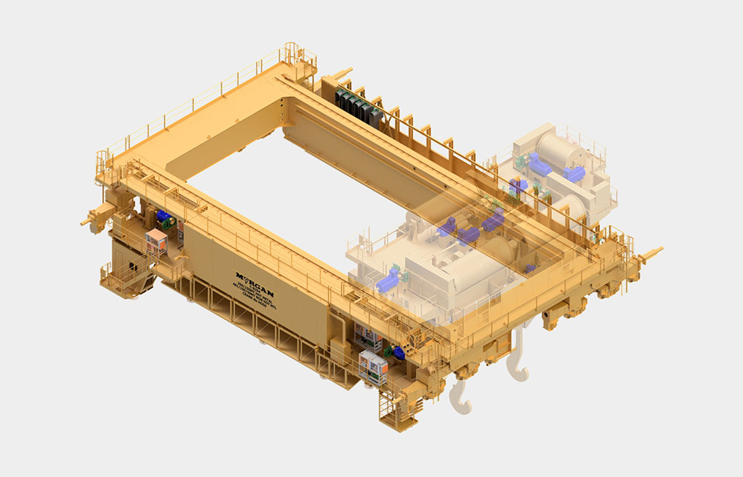
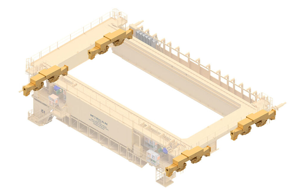
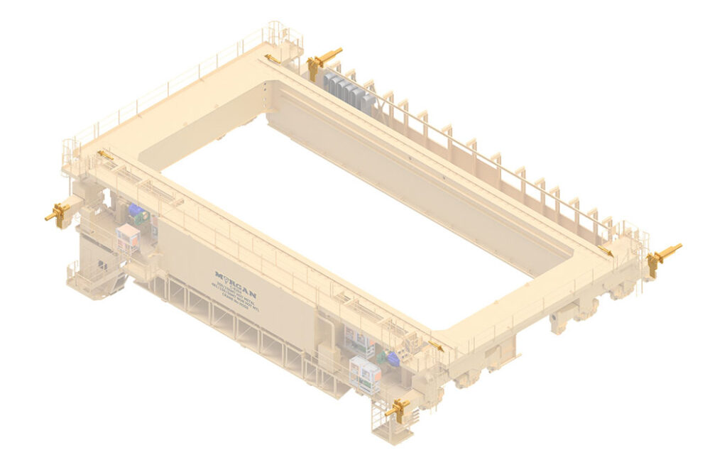
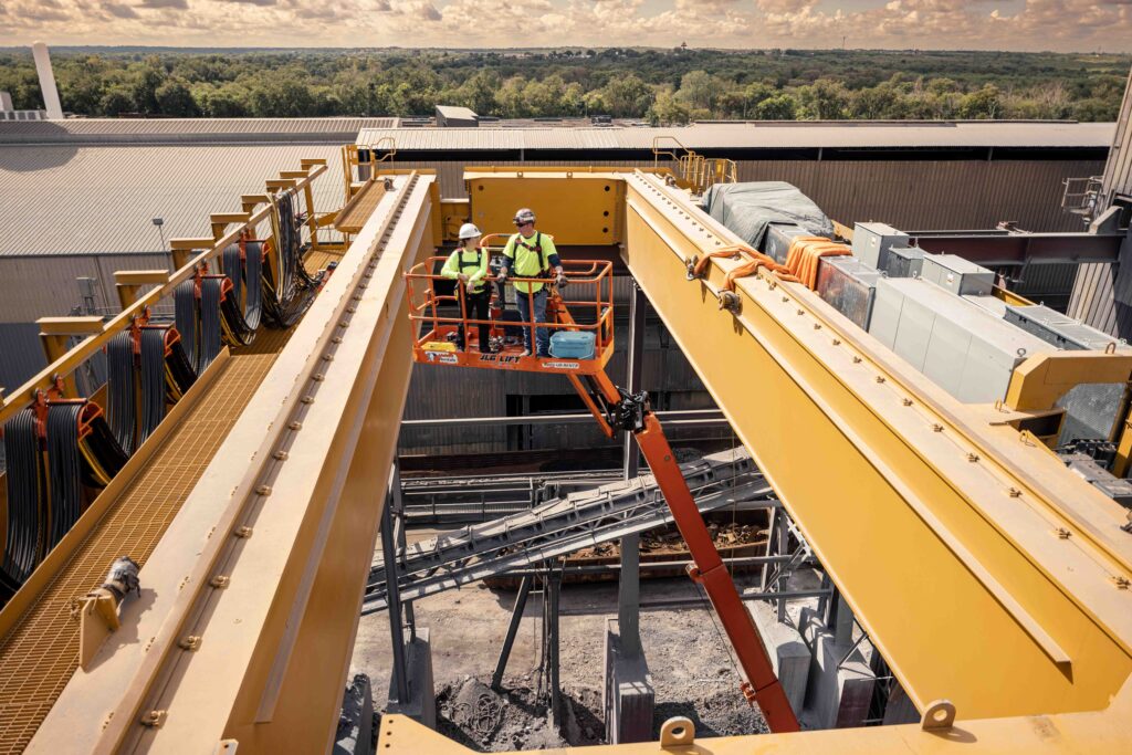
A bridge is the main structure of an overhead bridge crane. It supports the trolley and load by spanning the width and moves the length of the building, providing the second horizontal motion of an overhead crane.
The layout of a bridge remains consistent across most overhead cranes.
Bridge Crane Components
- Girders
- End Tie
- Wheel Equalizer Arrangements (Yokes, Trucks, Wheel Assemblies)
- Bumpers
- Footwalks
- Festoon/Power Track
- Mains Cage
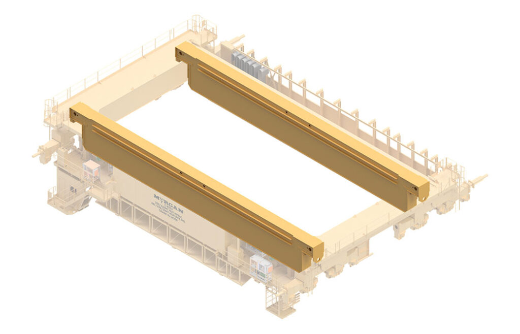
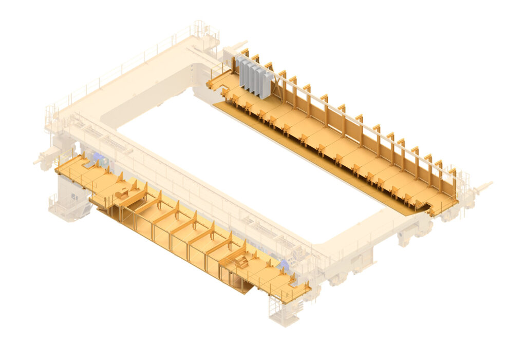
Girder
The girder is a welded box structure that holds the rail on which the trolley rides. Bridge cranes will commonly feature two girders connected by an end tie. The girders also consist of a notch in each corner where the wheel equalizer arrangements are connected.
The type of girder is decided by what the expected load and environment will be.
Types of girders:
- Conventional: rail centered over girder section
- Torsion: rail off-set usually over the inner web of girder section
- Walk-in: typically a torsion with cutouts that allow people to walk through while also housing the electronics
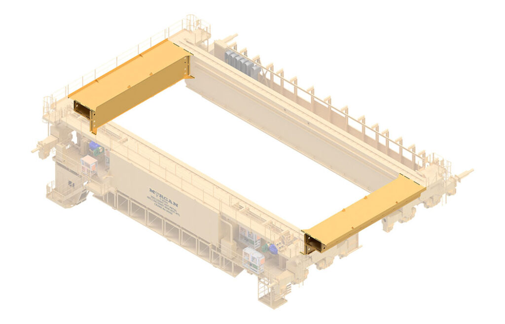
End Tie
An end tie on an overhead bridge crane is a welded structure at the ends of the girders. End ties are typically bolted to the girders. The purpose of the end ties is to maintain the squareness of the crane’s bridge and ensure the crane does not skew as it travels down the runway. This component also houses electrical wiring that connects the controls to the festoon/power track.
Wheel Equalizer Arrangements
Located in each corner of the bridge is a wheel equalizer arrangement. This arrangement consists of yokes, trucks, and wheel assemblies. This combination is responsible for bearing the weight of the crane and the lifted load uniformly to the building rail.
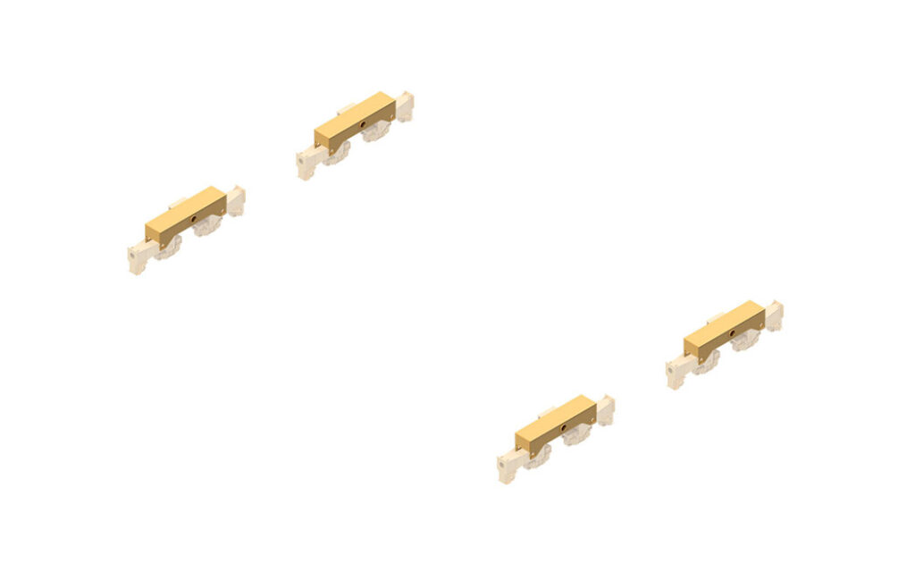
Yokes
When the weight and capacity of the crane become very high, yokes are connected to the ends of the girders at the notch. The yokes are a bridge crane part that allows for multiple trucks and in turn, hold more wheel assemblies.
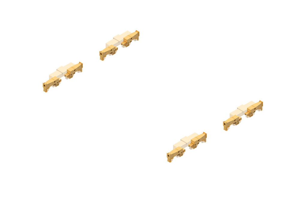
Trucks
Trucks hold two wheel assemblies. It is not necessary to always have yokes. In lighter cranes, the truck can be connected directly to the girder notch whereas, for heavier cranes, the truck can be connected to the yoke.
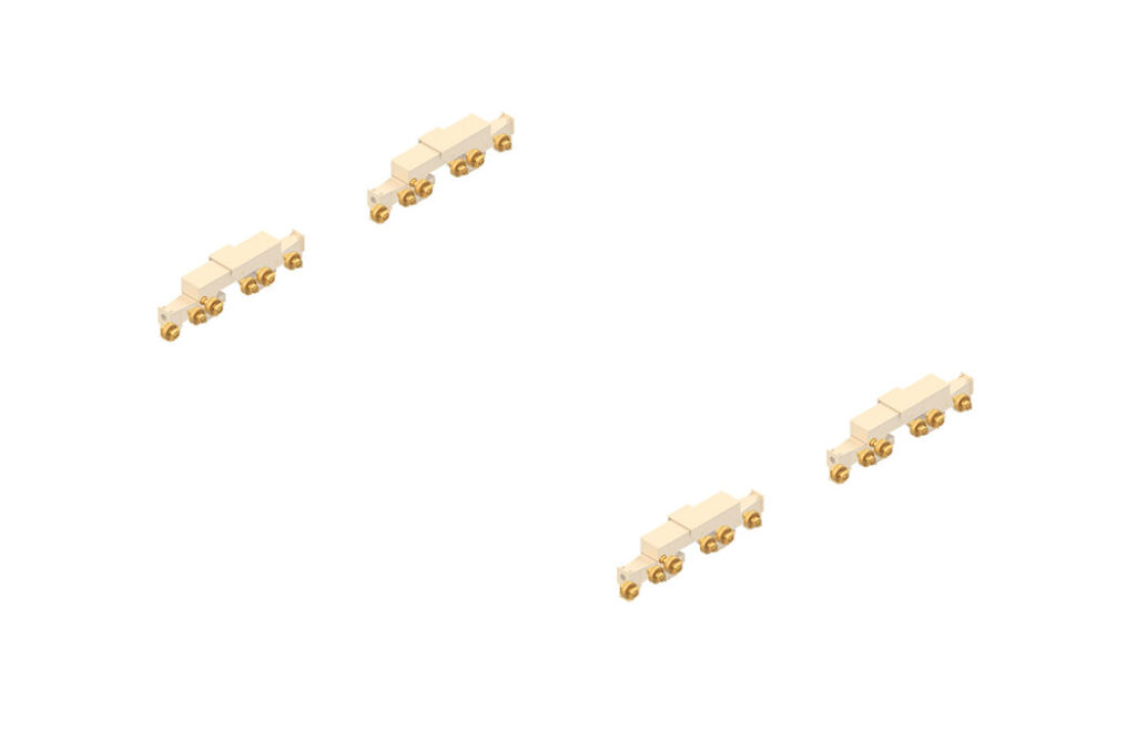
Wheel Assemblies
Housed by the frame, the wheel assemblies enable the bridge’s horizontal movement along the building rails. Typically, overhead bridge cranes are equipped with four, eight, twelve, sixteen, twenty-four, or thirty-two wheels. However, there can be any number of pairs of wheels on a bridge that come in different configurations. A minimum of one-fourth of the total number of wheels are to be driver wheel assemblies while the remaining sets are idler wheel assemblies. The driver wheel assemblies are divided equally along the sides of the crane to prevent skewing of the bridge.
Bumpers
A very important feature of a bridge crane are the bumpers, which are typically at each corner of the bridge. This part of the overhead crane serves to absorb energy caused by impacts as a crane reaches the end of its permitted travel distance. Bumpers can also be seen at the end of the trolley’s rail on top of the bridge. Depending on the circumstances, the bumpers are hydraulic, spring, or rubber material. These help to prevent devasting crane collisions and building damage.
Footwalks
Footwalks give crane operators and maintenance technicians access to critical crane components that require frequent service and inspections. It also provides support to the festoon/power track, control house or control cabinet, and other equipment.
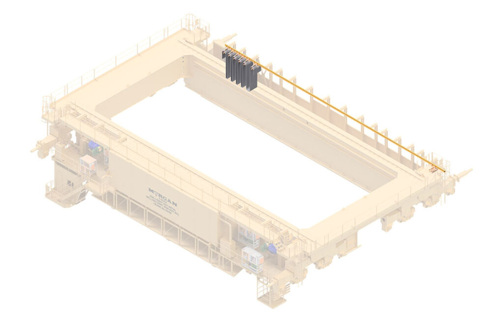
Festoon vs. Power Track
In general, a festoon or power track is used to provide a flexible power connection from the bridge control to the trolley.
Both systems are used to provide power to the trolley and allow it to pull the wiring with it as it moves across the bridge. Festoons are simpler to maintain but require a larger vertical footprint. Comparatively, power tracks are more compact and usually provide space for more equipment or stairs versus ladder access.
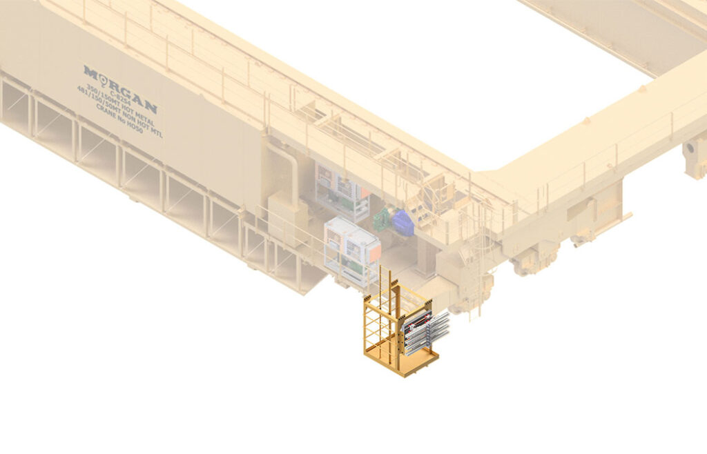
Mains Cage
The mains cage is located near the control house and provides maintenance access to the collectors, which are sliding conductors to supply power from the building onto the crane.
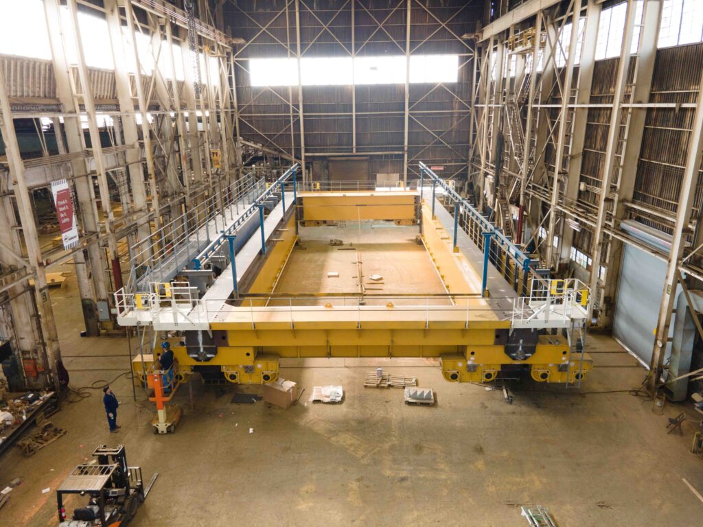
How a Bridge is Designed
When engineers sit down to design a new overhead crane’s bridge, they follow certain patterns. It is vital to know what space the bridge crane system will be housed in. The constraints of space will affect the layout.
Morgan cranes utilize a robust design that is meant to last for years. Though these cranes will be made for the needs a customer outlines now, our overhead bridge cranes can be used to accommodate unforeseen jobs customers will need to accomplish in the future.
Customize a Crane for Your Company
Now that you have learned the seven main components of a crane’s bridge: girders, end tie wheel equalizer arrangements, bumpers, footwalks, festoon/power track, and mains cage, make sure to follow along on Facebook, Instagram, and LinkedIn as we tackle the next two parts of an overhead crane in our upcoming Piece by Piece series.
Ready to elevate your lifting capabilities to new heights? Contact us to discuss how Morgan, an industry-leading bridge crane manufacturer, can custom engineer a crane solution that perfectly suits your unique needs.
